Radio
Frequency
Communication-Electronics
Course (RFCEC)
Course
Updated:
12/29/2016
This cover page is designed to be viewed with a monitor
screen resolution set for
1680 x 1050
The
course "Table
of Contents" link is at the bottom of this cover page introduction.
Creator Welcome Letter:
Congratulations
Welcome
and congratulations on your decision to use my Radio Frequency
Communication-Electronics Course (RFCEC), a self study distance-learning course
created, developed and provided by Erich Gugle. By using this course, you
have shown a desire to improve yourself and learn new skills, or improve those
skills you may already possess. If you are licensed in the Federal
Communication Commission (FCC), Amateur Radio Service (ARS) it
will enhance your
participation and
enjoyment. This course will provide you with instructions in the Fundamentals of
Direct Current Electricity, Alternating Current Electricity, Analog Electronics,
Digital Electronics, Telegraphy and Telephony Radio Frequency
Communication-Electronics (RFCE), tailored for use in the Federal Communication
Commission (FCC), Amateur Radio Service (ARS).
Your
Personal Characteristics
·
YOU ARE
PROPERLY MOTIVATED.
You have
made a positive decision to get training on your own. Self-motivation is perhaps
the most important force in learning or achieving anything. Doing whatever is
necessary to learn is motivation. You have it!
·
YOU SEEK
TO IMPROVE YOURSELF.
You have a
desire to learn new skills and improve those skills you already possess. When
you improve yourself, you improve the FCC ARS!
·
YOU HAVE
THE INITIATIVE TO ACT.
By acting
on your own, you have shown you are a self-starter, willing to reach out for
opportunities to learn and grow.
·
YOU
ACCEPT CHALLENGES.
You have
self-confidence and believe in your ability to acquire knowledge and skills. You
also have the self-confidence to set goals and the ability to achieve them,
enabling you to meet every challenge.
·
YOU ARE
ABLE TO SET AND ACCOMPLISH PRACTICAL GOALS.
You are
willing to commit time, effort, and the resources necessary to set and
accomplish your goals. These personal and professional traits will help you
successfully complete this distance-training course.
Course Introduction:
This Course
consists of '4' Sections containing '66' Chapters which have a total of '1894'
Lessons:
-
Section-1 has '10'
Chapters with '222' Lessons
-
Section-2 has '15' Chapters with '873' Lessons
-
Section-3 has '34' Chapters
with '457' Lessons
-
Section-4 has '07'
Chapters with '342' Lessons
In Section-1 and
Section-2 each Chapter
contains multiple
Lesson Plans with the same subject title that are
numerically listed in
progressive order (i.e.; 001 ~ 099 etc.). Each
Lesson Plan
is a complete topic in itself and leads into the next numerically listed Lesson
Plan.
Anyone
choosing to read any specific Lesson Plan, will garner knowledge concerning
the subject matter,
however
it is suggested that you do not read identically titled and numerically listed
Lesson Plan Subjects
in a 'cherry picking' style, because
you will not gain the knowledge in an appropriate order.
One discrete topic
concept is examined per lesson, and each lesson carries an illustration that
graphically depicts the topic being covered. Individual
lessons are taught in incremental steps and each lesson topic treatment prepares
the student for the next topic.
As a result of this
treatment, neither the text nor the illustrations are relied on solely as a
teaching medium for any given topic. Both are for every topic, so that the
illustrations not only complement but reinforce the text. In addition, to
further aid the student in retaining what they have learned, the important
points are summarized in text form on the illustration.
This unique simplification of an ordinarily complex
subject, the exceptional clarity of illustrations and text, and the plan of
presenting one basic topic concept at a time, without involving complicated
mathematics, all combine in making this course a better and quicker way to teach
and learn Fundamentals of Electricity, Fundamentals of Electronics and
Fundamentals of Radio Frequency
(RF) Communication-Electronics.
This unique treatment allows the course to be used as a
convenient review text. 'Color' is not used for decorative purposes, but to accent
important points and make the illustrations meaningful.
In keeping with good teaching practice, all technical
terms are defined at their point of introduction so that the student can proceed
with confidence. Key words for each topic are made conspicuous by the use of
'italics'. Major points covered in prior lessons are often reiterated in later
topics for purposes of retention. This allows not only the smooth transition
from lesson to lesson, but the reinforcement of prior knowledge just before the
declining point of one's memory curve.
In Section-3 and
Section-4 there are some Chapters that contain many Lessons that are complete
books in themselves.
All
the Lesson Plans are posted in either Adobe Acrobat
(.pdf) or Image (.jpg)
file extension formats
for easy viewing on-line or downloading to your personal
computer
and are provided as a 'one-stop-shop'
location to find them.
Files with (.jpg) file extension format should open with any Microsoft Operating
System
Program and files with (.pdf) file extension format require either the 'Full' Adobe Acrobat
Program or the
"Free" Adobe Acrobat Reader Program which can be downloaded at the URL listed here:
http://get.adobe.com/reader/.
I do not offer a way to
download the entire course as
"One File", because I am
periodically editing, updating
and adding lessons, which would make any previous download outdated. Check back
often and look at the date of update on this introduction page.
Course
Structure:
Preface:
Creator Welcome Letter, Creator Biography and Creator Experience
Section-1:
Fundamentals of
Electricity [Direct Current (DC) and Alternating Current (AC)]
Section-2:
Fundamentals of
Electronics [Analog (A) and Digital (D)]
Section-3:
Fundamentals of
Radio Frequency
Communication-Electronics
[Radiotelegraphy (RTGY) and Radiotelephony (RTPY)]
Section-4:
Fundamentals of Ground Radio Maintenance [Test
Measurement Diagnostic Equipment (TMDE), Reading Schematics, Troubleshooting,
and Soldering]
Course Development:
I am a United States Marine,
mandatorily retired
from
United States Marine Corps
Active Duty
Military Service.
(In
accordance with
Public Law and Department of Defense Regulations,
Mandatory retirement from Active Duty Military Service is legislated at 30 years).
I
completed a
total
of '30 years' of Active Duty from
June 30, 1969 to July 1, 1999.
During a portion of my Active Duty Service, I was an Instructor
at the
Marine Corps Communication-Electronics Schools (MCCES).
As a
MCCES
instructor,
I taught
United States Marines,
Parts-1, 2, 3 and 4B (listed below), of the Marine Corps Communication-Electronics Maintenance Course (MCCEMC). (Symbol @ indicates which parts of the MCCEMC I taught.)
The Marine Corps Communication-Electronics Maintenance Course (MCCEMC)
consisted of the following curriculum:
Part-1. Fundamentals of Electricity [Direct Current
(DC) and Alternating Current
(AC)]. @
Part-2. Fundamentals of
Electronics [Analog (A) and Digital (D)].
@
Part-3. Fundamentals of
Radio Frequency Communication-Electronics [Radiotelegraphy
(RTGY) and Radiotelephony (RTPY)].
@
Part-4A.
Fundamentals of
Air Radio Maintenance (ARM): MOS - 2851 Air Radio Technician.
Part-4B.
Fundamentals of
Ground Radio Maintenance (GRM):
MOS - 2841 Ground Radio Technician. @
Part-4C.
Fundamentals of
Microwave Radio Maintenance (MRM): MOS - 2831
Microwave Radio Technician.
Note:
All
Students were taught Parts-1, 2 and 3, but were only taught one of the three Sections of Part-4,
depending on which Military Occupational Specialty (MOS)
number they were assigned.
During my duty as an instructor, I concluded that the curriculum I taught could be modified
and developed into a course of instruction for use
as
an aid to Mentor individuals
interested in obtaining a
Federal Communication Commission (FCC),
Amateur Radio Service (ARS),
Primary Station License Grant (PSLG) and Amateur Operator
License Grant (AOLG).
I
created my RFCEC
by
modifying
parts of the
MCCEMC
curriculum.
My goal for creating my RFCEC was to help
individuals ‘learn new skills’ and/or ‘improve skills they may already possess’.
I formally taught the MCCEMC for 4 years (1979 ~ 1983) and afterwards my created RFCEC
for 29 years (1983 ~
2012) for a
grand total of 33 years teaching. RFCEC students
included individuals
of the
General Public
interested in obtaining
an FCC ARS PSLG and AOLG
and individuals who already held an FCC ARS PSLG and AOLG, interested in
improving their knowledge level or
upgrading their existing AOLG Class.
Since initial creation and
over the years
of teaching my RFCEC, I continued to improve the course by adding
additional materials from various different sources. The
different
materials used to improve the RFCEC were
curriculum
from my Civilian College Course Lesson Plans and Notes,
U.S. Department of Energy (DOE) documentation, U.S. Department of the Navy (DON) Marine Corps
Institute (MCI) Courses,
U.S. Department of the Navy (DON)
Navy Electricity and Electronics Training Series (NEETS) Courses, and
documentation written by other Authors.
The documents
written
by other authors,
were either obtained from the individual authors directly,
or from
the public domain.
The RFCEC Lesson Plans consist of 79%
mine, and 21%
from other authors.
I no longer formally teach my RFCEC, but offer
it "FREE"
as an "Independent
-
Self-Study
Distance Learning Course".
The RFCEC is not affiliated with nor sponsored by, the American Radio Relay League (ARRL),
any Amateur Radio Association,
Amateur Radio
Club,
Amateur Radio
Society, or College/University.
Course Creator Information:
Erich Gugle
Email: K4RFE@rfcec.com
MBABM,
MSEE,
BSEE, BSET, AASEET


2009 - Age 62 (Motorola: RF
Communication-Electronics; Senior Principal Engineer)
Department of the Navy (DON), Unites States Marine Corps (USMC), Official Seal
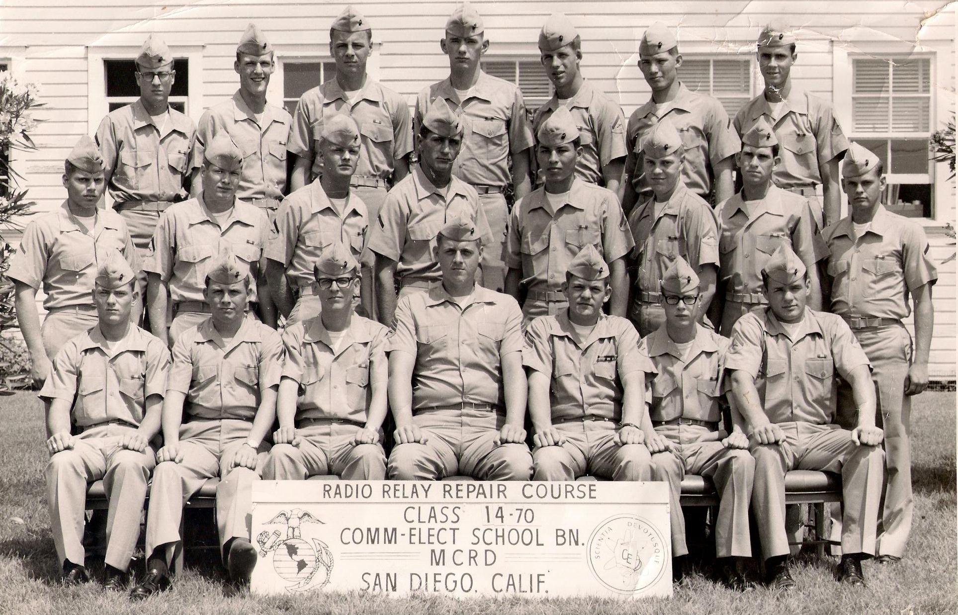
1970 - Age 23
[USMC: Marine Corps Communication-Electronics Schools (MCCES),
Student; Radio Relay Repair Course
(RRRC), I am standing in the second Row, first on the viewers left]
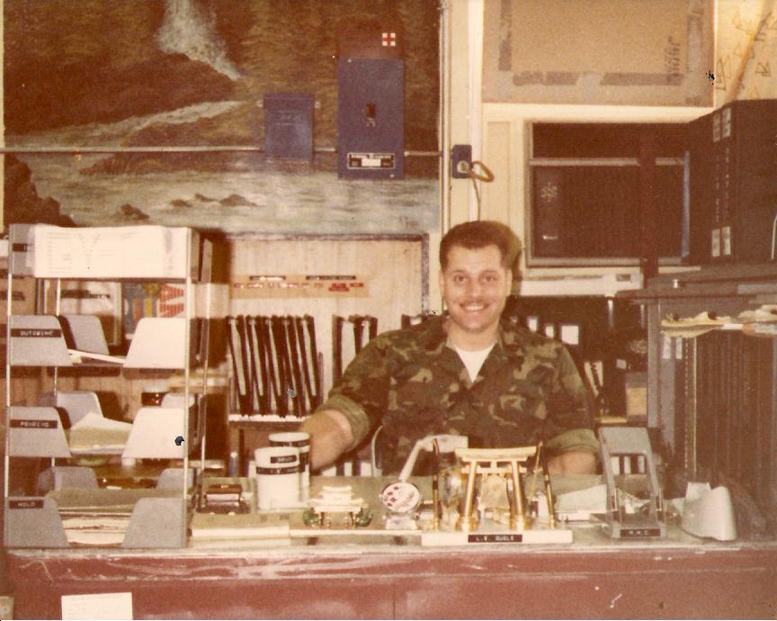
1979 - Age 32 (USMC: RF Communication-Electronics; Maintenance Chief &
Operations Chief)

USMC MCCES Logo
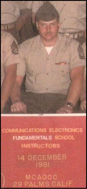
1981
- Age 34 (USMC: MCCES Instructor)
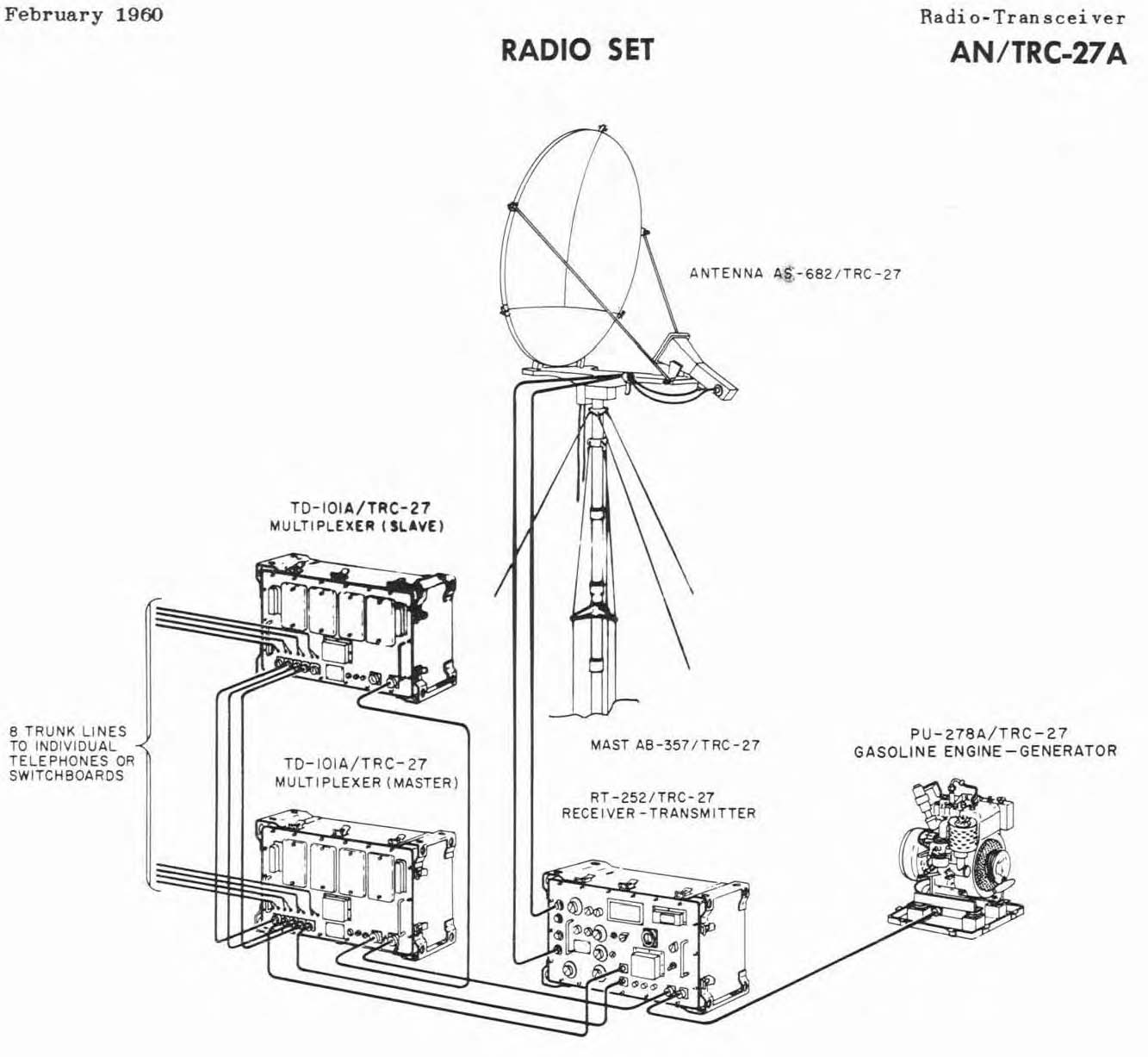
Radio Set AN/TRC-27A
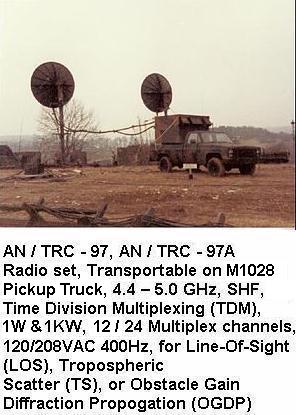
Radio Set AN/TRC-97
Electric and Electronic Fundamentals:
Georg Simon Ohm's
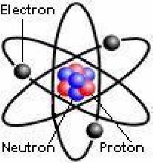
Atomic Structure
and James Prescott Joule's Laws
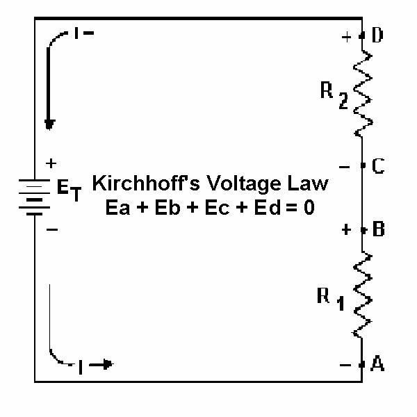
Gustav Robert Kirchhoff's
Law
Physics Axioms:
- Matter is defined as anything that occupies space
and has weight. It may be found in any one of 'three states':
Gas, Liquid and Solid.
Elements are the basic materials that make up all matter
and they can be combined to produce Compounds.
The Molecule is the smallest particle that a
Compound can be reduced to before it breaks down into its Elements.
The Atom is
the smallest particle that an Element can be reduced to and still keep the
properties of that Element. It contains three types of subatomic particles
that are of interest in electricity:
Electrons, Neutrons and Protons.
Electricity is produced when Electrons are
freed from their atoms.
Direct Current (DC) Circuits:
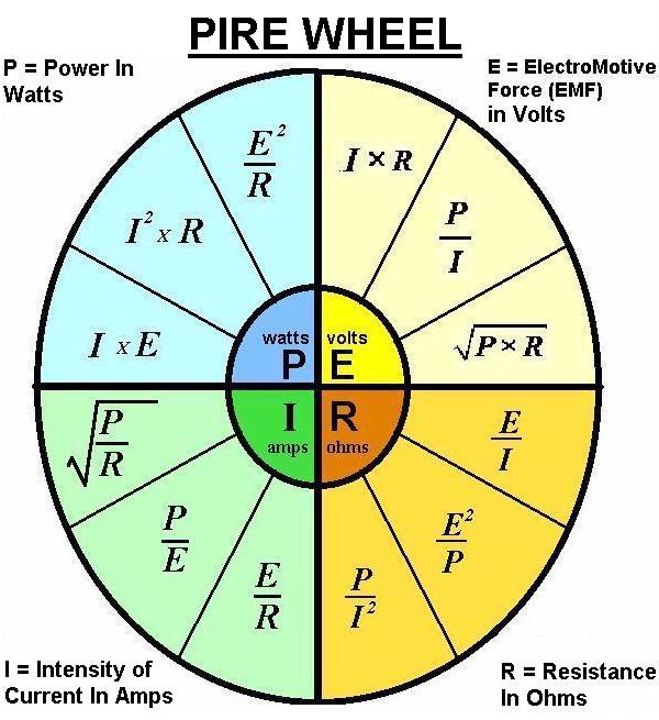
- The circuit Current (I) is directly proportional to
the Voltage (E) an inversely proportional to the Resistance (R). Total circuit Resistance (R) is determined
by the value of the individual Resistors contained within the circuit.
When '1' volt (E) of
Electromotive Force (EMF), forces '1' ampere of current (I) through '1' ohm of resistance (R)
'1' watt of power (P) is dissipated. [Georg
Simon Ohm's Law]
-
Electrical Power (P) is measured in Watts (W),
and is
the Current (I) times the Voltage (E). [James Prescott
Joule's Law]
-
The algebraic sum of all voltages in a loop must
equal zero. [Kirchhoff's Voltage Law (KVL)]
-
The algebraic sum of all currents entering and
exiting a node must equal zero. [Kirchhoff's Current
Law (KCL)]
Alternating Current (AC) Circuits:
- The circuit Current (I) is directly proportional to
the Voltage (E) an inversely proportional to the Impedance (Z).
- Total circuit Impedance (Z) is determined
by the Frequency (F) in Cycles per Second (CPS) of the Alternating Current (AC) and
the values of any 'individual' or
'combination' of the following contained within the circuit;
- Resistors will cause an impedance to the
circuit current flow from their Resistance (R).
- Inductors will cause an impedance to the
circuit current flow from their Inductive Reactance (XL).
- Capacitors will cause an impedance to the
circuit current flow from their Capacitive Reactance (Xc).
- Examples of
Impedance (Z) are: (Z = F + R) or (Z
= F + XL) or (Z =
F + Xc) or (Z
= F + R + XL) or (Z =
F + R + Xc) or (Z
= F + XL + Xc) or (Z = F + R + XL
+ Xc).
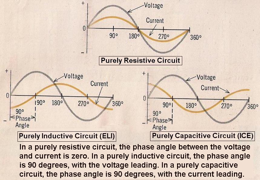
Alternating Current (AC)
Circuits, Relationships of Voltage (E) and Current (I):
- In a Purely Resistive (R) Circuit, the Voltage (E) is "In phase" with the Current (I).
- In a Purely Inductive (L) Circuit, the Voltage (E) "Leads" the Current (I) by 90 degrees.
- In a Purely Capacitive (C) Circuit, the
Current (I) "Leads" the Voltage (E) by 90 degrees.
- A Simple way to remember the
Phase Angle relationships is by the
phrase
"ELI the ICE man".
- In
the word "ELI", the letter (E) for Voltage, comes before or "Leads" the letter
(I) for Current, and the letter (L) means Inductive circuit.
- In the word "ICE",
the letter (I) for Current, comes before or "Leads" the
letter (E) for Voltage, and the letter (C) means Capacitive circuit.
Electric and Electronic Components:
Electronic - Active Device Components
Electronic - Active Device Components
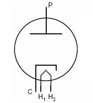
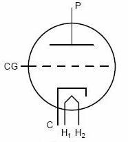
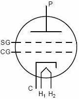
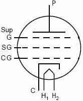
Electron Tubes:
Solid State
Semiconductors:
Electric and
Electronic - Passive Device Components Made in a Glass or Ceramic/Metal Vacuum
Made from Germanium or Silicon
CAPACITOR (C) INDUCTOR (L) RESISTOR (R) DIODE TRIODE TETRODE PENTODE
DIODE BJT JFET MOSFET


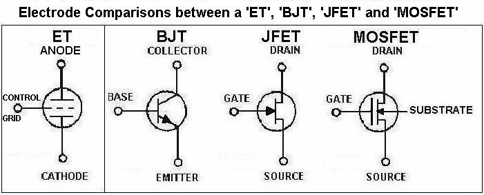
Abbreviation Legend: ET = Electron Tube, BJT
= Bipolar Junction Transistor, JFET
= Junction Field Effect Transistor,
MOSFET
= Metal Oxide Semiconductor Field Effect Transistor
[Originally
called a (IGFET) = Insulated Gate Field Effect Transistor]
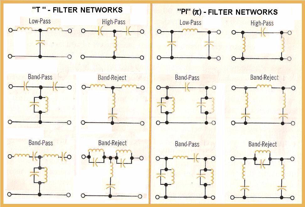
Low-Pass,
High-Pass, Band-Pass and Band-Reject, Constant - 'K' and 'M' - Derived, 'T', and 'Pi' Filter Network Diagrams
'Three'
Sample Lesson
Plans
from
Section-3
Provided Below:
Sample Lesson # 1
Examples of an
Amateur Radio
Service,
Radio Frequency Communication-Electronics Fixed Station,
properly setup
to operate
Radiotelegraphy and Radiotelephony Modes:
[MF (160 Meters),
HF (80 – 10 Meters) and VHF (6 Meters)]
Figure-1;
illustrates an
‘Example’ Amateur Radio Service,
Radio Frequency
Communication-Electronics
Fixed Station,
properly setup to operate
Radiotelegraphy or Radiotelephony
modes, and the necessary interconnecting
Coaxial Cable RF Feedlines
used with
'One Transceiver, One Manual Tune
RF Power Amplifier, One RF Power / VSWR
Meter, One Manual Tune
Tuner, and Two Loads
(1-Active
Load and 1-Dummy Load)'.
The coaxial cable switch is used
so that the desired Load may be selected.
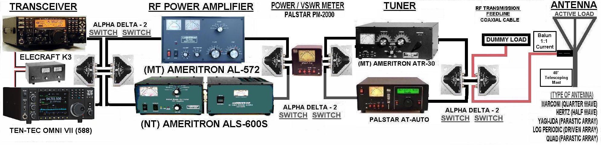
Figure-1

Figure-2;
illustrates an
‘Example’ Amateur Radio Service,
Radio Frequency
Communication-Electronics
Fixed Station,
properly setup to operate
Radiotelegraphy or Radiotelephony
modes, and the necessary interconnecting
Coaxial Cable RF Feedlines
used with 'One Transceiver,
One Automatic Tune
RF Power Amplifier, One RF Power / VSWR Meter, One Automatic Tune
Tuner, and
Two Loads
(1-Active
Load and 1-Dummy Load)'.
The coaxial cable switch is used
so that the desired Load may be selected.
Figure-2

Figure-3;
illustrates an
‘Example’ Amateur Radio Service,
Radio Frequency
Communication-Electronics
Fixed Station,
properly setup to operate
Radiotelegraphy or Radiotelephony
modes, and the necessary interconnecting
Coaxial Cable RF Feedlines
used with
'Two Transceivers, Two
RF Power Amplifiers (One Manual Tune
and One
Automatic Tune),
One RF Power / VSWR Meter, Two Tuners (One
Manual
Tune
and One
Automatic Tune),
and Two Loads
(1-Active
Load and 1-Dummy Load)'.
The coaxial cable switches are used to select the desired equipment and
the desired Load.
Figure-3
In Figure 3, above any one of
following combinations may be used with either Transceiver:
a. Manual Tune
RF Power Amplifier and Manual Tune
Tuner.
b. Manual Tune
RF Power Amplifier and Automatic Tune Tuner.
c. Automatic Tune
RF Power Amplifier and Automatic Tune Tuner.
d.
Automatic Tune
RF Power Amplifier
and Manual Tune
Tuner.
Notes
for Figures 1, 2 and 3:
- Some
Tuners contain a built in RF Power / VSWR Meter and if this is the case the
external RF Power / VSWR Meter shown between the RF Power Amplifiers and
Tuners may be eliminated.
- Most
Tuners have connections for use with 'Unbalanced' 50-Ohm Characteristic
Impedance (Zo) Coaxial Cable RF Feedline. Some Tuners have a
built-in 'Balun' that allows it to be used with 'Balanced' 300-Ohm,
450-Ohm, or 600-Ohm Characteristic Impedance (Zo) RF Feedlines.
- Some
'older' Electron Tube RF Power Amplifiers, placed in-line after the
Transceiver, don’t have a ‘Fixed’ 50-Ohm Input Impedance Coupling Network. If this is the case, a Transceiver with a built in Automatic
Antenna Tuner, can be used to match the Transceiver's 50-Ohm Output
Coupling Network Impedance through 50-Ohm Characteristic Coaxial Cable, to the
external Electron Tube RF Power Amplifiers input impedance for an optimal transfer of RF power from the
Transceiver to the input of the electron tube or tubes.
Sample
Lesson # 2
Code of Federal Regulations,
Title 47 - Telecommunications,
Section 1 - Federal Communications Commission,
Part 97 - Amateur Radio Service,
Subpart A - General Provisions,
Section 97.1 - Basis and Purpose.
The rules and regulations in this part are
designed to provide an amateur radio service having a fundamental purpose as
expressed in the following principles:
a.
Recognition and enhancement of the value of the amateur service to the public as a voluntary noncommercial communication service, particularly with respect to providing emergency communications.
b. Continuation and extension of the amateur’s proven ability to contribute to the advancement of the radio art.
c.
Encouragement and improvement of the amateur service through rules which provide
for advancing skills in both the communications and technical phases of the art.
d. Expansion of the existing reservoir within the amateur radio service of trained operators, technicians, and electronics
experts.
e.
Continuation and extension of the
amateur's unique ability to enhance international goodwill.
Sample Lesson # 3
Amateur Radio Service,
Station Operation Procedures
Recommended - Do's
1.
Develop good
operating practices. Set an example for other operators and you will be doing
your part in helping insure the continuance of our long
and proud tradition of self-regulation.
-
Aspire to
comply with all the applicable
Federal Communication Commission
(FCC), Title 47, Section 1, Rules and Regulations contained
in Part 2
(Frequency Allocations
and Treaty Matters; General Rules and Regulations) and Part 97 (Amateur Radio
Service).
A good operating guide to follow
is “The Amateur Radio
Service Operator’s Code”
written in 1928 by W9EEA Paul M. Segal.
-
If you are a repeater user, here is
a URL of a professional sounding radio announcer (Mr. Bill Hamilton) giving a
narration of good repeater operating practices/procedures. Information courtesy
of W8RXX John Perone.
http://www.repeater-builder.com/repeaterisms/repeaterisms.html
2.
Set a good example
of on-the-air operations for other Amateur Radio Service Operators and especially for Short Wave Listeners (SWL) who may be thinking about becoming an
Amateur Radio Service Operator.
3.
Try to keep track of
everyone involved in the Conversation on Telephony (AM/FM/SSB)
or Telegraphy (CW).
When involved in a ‘round-table’
style Conversation
on Telephony (AM/FM/SSB)
or Telegraphy (CW), make it clear at the end of each transmission
which station is expected to transmit next.
-
Hopefully someone has assumed the role of
"traffic director" to make sure everyone has a chance to contribute to the
discussion. If not, don't hesitate to do it yourself.
5.
Always be polite regardless of the
circumstances.
-
If not, avoid transmitting.
6.
Look for
opportunities to "Mentor" newly licensed or license class upgraded Amateur Radio
Service Operators when you hear them on the radio frequency bands.
- Welcome them,
solicit their questions and give them pointers on good operating practices.
7.
Be a good listener.
-
It will help you better organize your thoughts before transmitting.
8.
Reply to a CQ
call, or call CQ yourself.
- It helps keep alive the magic of Amateur Radio.
9.
Make a conscious
effort to identify your Primary Station Call Sign at the end of your
transmission or at every 10 minute interval throughout a conversation, which ever comes
first.
10.
Speak clearly
and slowly, especially when giving your call sign to someone you have never
worked before.
- For clarity use the International Phonetic
Alphabet to spell out your call sign when making a contact for the first time with a new station.
Amateur Radio Service,
Station Operation Procedures
Recommended - Don'ts
1. Don't transmit on any frequency, before first determining that the frequency you
want to use is clear, as well as the adjacent frequencies plus and minus (+/-)
the Band Width (BW) of the emission mode you are going to use.
a.
Example of appropriate
procedures:
i.
If you want to use the
frequency of 7.128 MHz for Single Side Band Suppressed Carrier - Amplitude
Modulation (SSBSC-AM) operations (emission designator 2K70/J3E), vary your VFO
up to the frequency of 7.131 MHz (+3 KHz) and down to the frequency of 7.125
MHz (-3 KHz) to see whether those frequencies are in use by other operators in
a conversation.
ii.
Then before transmitting on
7.128 MHz, listen for a short time to see whether it is being used or not. If
it seams to be clear, ensure that it is, by transmitting the question “Is this
frequency in use, is 7.128 MHz in use, this is (Your Station Call Sign)”? Ask
this question at least twice before calling a specific station or calling a
CQ.
iii.
This procedure must be
followed so that your Single Side Band Transmissions, 3rd Order IMD Band Width
on 7.128 MHz, does not interfere with other conversations on adjacent
frequencies above and below. If there are operators within +/- 3 KHz, your 3rd
Order IMD will be within their Receiver's Band Pass Filter (BPF) Pass Band
(PB).
b.
Never
assume a frequency is clear even if nobody is transmitting at the time you
have been listening. There may be operators that are using the frequency
standing by, awaiting the return of another operator who has stepped away for
a short time to get a refreshment, use the toilet, answer a telephone call, or
answer a question from a family member.
2. Do not transmit closer to a 'Band Edge', 'Emission Mode - Band Segment Edge',
'Operator Class - Band Segment Edge' or 'Another Ongoing Conversation" than:
-
‘100 Hz’ using
Emission Designator
‘100HA1A'
[‘ON’ and ‘OFF’ keying Carrier Wave (CW) Telegraphy]
-
‘3 KHz’
using
Emission Designator
‘2K70J3E’
[Single
Side Band Suppressed Carrier -
Amplitude
Modulation
(SSBSC-AM) Telephony]
-
'6 KHz’ using
Emission Designator
‘6K00A3E’ [Double
Side Band Full Carrier -
Amplitude Modulation
(DSBFC-AM)
Telephony]
-
‘16 KHz’
using
Emission Designator
‘16K0F3E’
[Frequency
Modulation (FM) Telephony]
-
‘19 KHz’
using
Emission Designator
‘16K0G3E’
[Phase Modulation (PM) Telephony]
3.
Don't interrupt an ongoing 'Private Conversation', on Radiotelephony (Voice) or
Radiotelegraphy (Continous Wave = CW) unless you have requested permission to
join.
-
If
you are not a part of the conversation between the individuals currently
using the frequency and would like to join, give your
“call sign” between their
transmissions and wait to be recognized.
-
If
the operators using the frequency recognize your transmission, it doesn’t
mean that they have invited to join the conversation, it only means that
they have heard you and recognized your transmission. Don't just start
talking, be courteous and request permission to join the private
conversation.
-
Interrupting an ongoing 'Private Conversation', is extremely rude, whether
you do it 'In-Person' or 'Over-The-Air by Radio Transmission'.
-
If
your are invited to join the conversation ensure your comments have
something to contribute to the topic that was being discussed. It is
especially rude to make a transmission and change the subject.
4. Don't
interrupt an ongoing 'Private Conversation' on Radiotelephony (Voice) or
Radiotelegraphy (Continous Wave = CW), with any "Unsolicited Comment" about the
topic being discussed, either with a legal identified or illegal unidentified
transmission.
-
Interrupting an ongoing 'Private Conversation' with any 'Unsolicited Comment',
is extremely rude, whether you do it 'In-Person' or 'Over-The-Air' by Radio
transmission.
-
If you
make any 'Unsolicited Comment', either at the end of your transmission or within
10 minutes after your transmission, without identifying your Primary Station
Call Sign, fits into the category of an "illegal" unidentified transmission.
5. Don't
interrupt or ask to join an ongoing 'Private Conversation' on Radiotelephony
(Voice) or Radiotelegraphy (Continous Wave = CW) unless you can hear the
majority of the participants and the other operators can hear you.
-
The
reason you should do this is because, it is discourteous and unfair to the
individuals already currently in the conversation, because they would not be
able to hear your comments.
-
The best
procedure to determine whether you can hear all individuals involved, is to
listen to the conversation for at least 10 minutes and write down the Call Signs
of the Stations currently on frequency.
6.Don't
use the words "break" or “contact” when wanting to join an ongoing 'Private
Conversation' on Radiotelephony (Voice).
-
If you
are not a part of the conversation between the individuals currently using the
frequency and would like to join, give your
“call sign” between their
transmissions and wait to be recognized.
-
Don't use
the words "break", which when used as a verb means, “interrupt”, it does not
mean, “I want to join the conversation".
-
Don't use
the word “contact”, which when used as a verb means “communicate with”, it does
not mean, “I want to join the conversation".
-
If
however you have an "Emergency" or other "Urgent" situation, use the words
"break-break" to "interrupt".
7. Don't
use
Radiotelegraphy (Continuous Wave = CW) 'Q-Signals' such as QRT, QRZ, QSL, QSY,
QTH and 'Numbers' such as 73 or 88 using Radiotelephony (Voice) Communications.
-
Use normal 'Plain Language Words'
or Radiotelephone 'Prowords'.
-
'Q-Signals' and
'Numerical' abbreviations were developed for reasons of 'brevity' and are
appropriate using the
International
Morse Code in
Telegraphy 'On and
Off' Keying Carrier Wave (CW)
Data operations.
-
They were not developed
and are
not appropriate
for use when the mode of operation is on Telephony
(Voice) operations using
Dual Side Band Full Carrier -
Amplitude Modulation (DSBFC-AM), Single Side Band Suppressed Carrier - Amplitude
Modulation (SSBSC-AM), or both forms of Angle Modulation [Frequency Modulation
(FM) and Phase Modulation (PM)].
-
Some examples are listed below, however all
'Q-Signals' and 'Numerical' abbreviations
are not appropriate in
voice modes.
-
Don’t say by voice, the CW Q-Signal, “QRT?"
in interrogative form
which means: "Shall I stop sending?".
-
Don’t say
by voice,
the
CW
Q-Signal,
"QRT”
in
declarative form
which means: "Stop sending."
-
Don’t say
by voice,
the
CW
Q-Signal,
“QRZ?"
in interrogative form
which means: "Who is calling me?".
-
Don’t say
by voice,
the
CW
Q-Signal,
"QRZ”
in declarative form
which means:
"You are being called by ___."
-
Don’t say
by voice,
the
CW
Q-Signal,
“QSL?”
in interrogative form
which means: "I acknowledge
receipt".
-
Don’t say
by voice,
the
CW
Q-Signal,
"QSL"
in declarative form
which means:
"Can you acknowledge receipt?".
-
Don’t say
by voice,
the
CW
Q-Signal,
“QSY?”
in interrogative form
which means: "Shall I change to another frequency?".
-
Don’t say
by voice,
the
CW
Q-Signal,
"QSY"
in
declarative form
which means:
"Change to another
frequency."
-
Don’t say
by voice,
the
CW
Q-Signal,
“QTH?”
in interrogative form
which means: "What is your location?".
-
Don’t say
by voice,
the
CW
Q-Signal,
"QTH"
in declarative form
which means:
"My location is ___."
-
Don’t say
by voice,
the
CW
Number Code, “73”
in declarative form
which means: “Best Regards”.
-
Don’t say
by voice,
the
CW
Number Code,
"88" in
declarative form which means:
"Hugs and Kisses".
8.
Don't 'Tune and Load' any
Transmitter with an 'Electron Tube RF Power Amplifier (RFPA) Stage',
or 'Tune and Load'
any 'External Inline Electron Tube RF Power Amplifier (RFPA)' after the
Transmitter, using an Active Load
'Over-The-Air'.
-
Use a
50-Ohm 'Dummy Load' to 'Tune and Load' all Electron Tube Transmitters and
External Inline RFPA, which has a "Pi" or "Pi-L" configured Output Coupling Low
Pass Filter (LPF) Network.
-
Once the
Transmitter and any External Inline RFPA tuning is completed using the Dummy
Load, put any External Inline RFPA in 'standby'.
-
Use an
Impedance Matching Network (IMN) placed inline after the Transmitter
or after the External Inline
RFPA, and tune for a match between the IMN output Impedance (Z) of 50 ohms to
the 'Complex' input Impedance (Z) of the Active Antenna RF Feed Line.
-
An IMN is also referred to as an 'Antenna Coupler', 'Antenna System Coupler',
'Antenna Tuner', 'Antenna System Tuner', 'Transmatch' or just 'Tuner'.
-
When
matching the output impedance connected to an IMN, use the lowest output power
available from the Transmitter.
-
After the
appropriate IMN impedance matching is completed, increase the Transmitter output
power to the desired level and turn on any External Inline RFPA and switch to
the Active Load.
9.
Don't knowingly interfere with an ongoing Conversation on Radiotelephony (Voice)
or Radiotelegraphy (Continous Wave = CW) just because you are working a 'DX
Station' or 'Operating in a Contest', especially using split frequencies. (Note:
Refer to numbers 1 and 2 above)!
10.
Don’t operate in any fashion that is not in keeping with Good Amateur Practice.
Course
"Table of Contents" Link:
1.
Click on the link
below and it will list the
'Table of Contents'. (Recommend that your screen 'Zoom' level be increased to
200%)
2.
Click on the
'Preface' Title
and it will list the
'Contents'.
b. Click any 'Content' Title and it will 'open'.
3. Click
on any one of the
'Section'
Titles
and it will list the
'Chapter'
Titles.
4. Click
on any one of the
'Chapter' Titles
and it will list the
'Lesson Plan' Titles.
b.
Click on any one of the
'Lesson Plan' Titles and it will
'open'.
http://RFCEC.com/RFCEC